2008
Subaru WRX STi
Valentine 1
Radar Locator
Remote Display Installation
Enhancing my V1 installation, I installed the custom-made thin remote display that agravic makes and sells through eBay. Some of the steps are repeats of the V1 installation. Most are new. None are terribly difficult.
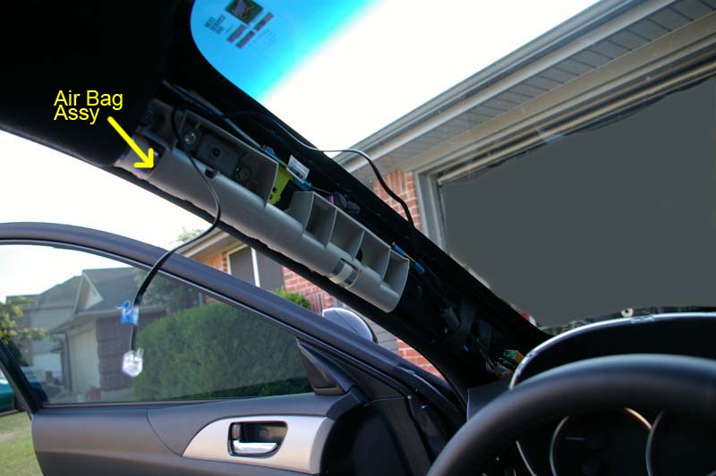
WARNING: You will be working near one of the side curtain air bags. Subaru often advises that you disconnect the negative terminal to the battery while doing this kind of work to avoid triggering the bag accidentally.
The Supplies you'll need for this installation are:
1. A Custom Thin V1
Remote kit from agravic (this
includes the remote mute button)
2. A 4 - 6 foot length of 4 wire (straight-through) phone line with RJ11 connectors
on each end
3. A "4 wire" RJ11 coupler
(if a male to female length of phone line can't be found for item #2)
4. 6 inches of 3M
Dual Lock
5. These instructions
The tools you'll need for this installation are:
1. Philips screwdriver
2. Flat blade screw driver
3. Wooden tongue depressor, Flat plastic trim tool, or long finger nail
The steps needed for this installation are:
1. Remove the map light
module
2. Remove the head liner retaining rivet
3. Remove the Pillar Trim
4. Remove the LH Instrument Panel Side Cover
5. Remove the Meter Visor Assembly
6. Loosen the Combination Meter Assembly
7. Remove the LH Ornament Panel & Air Vent Side Grill
8. Remove the lower steering column cowling
9. Route the wiring harness for the Custom Thin V1 Remote Display
10. Reassemble (reverse steps 1 though 8)
11. Mount the Remote Thin Display
and Mute Button
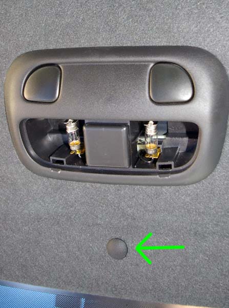
1. Remove the map light module
Installation begins with removing the map light module as we did when hard wiring the V1. Once you've dropped the map light module (no need to disconnect it), retrieve the Valentine junction box that you stored inside the headliner.
2. Remove the head liner retaining rivet
Next, pull the plastic rivet holding the V1 to the headliner.
3. Remove the Pillar Trim
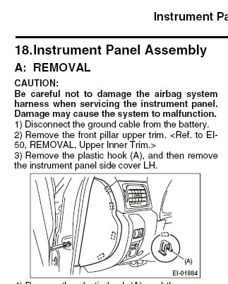
Remove the Pillar Trim as described in the Subaru shop manual
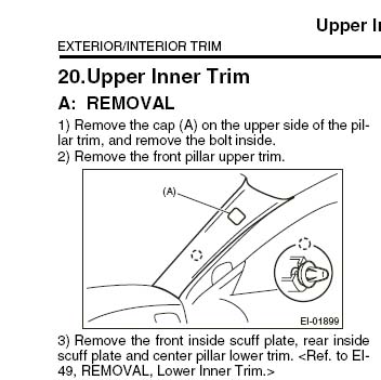
A. Removing the cap is where you need to be careful. A flat blade screw driver or other "hard" tool may damage the plastic. Using something like a wooden tongue depressor, a plastic trim tool, or long finger nails will help avoid damaging the finish. Pull the top edge first and then carefully pull it from its socket.
B. Using a philips screwdriver, remove the retaining bolt that is exposed under the trim cap.
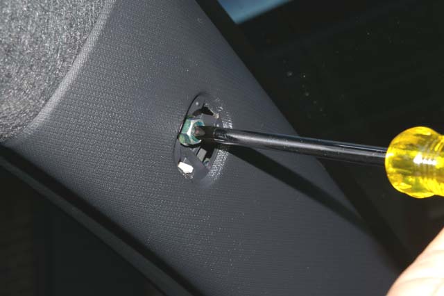
C. Working your fingers under the top, window-side edge of the pillar trim, lift it carefully away from the pillar.
D. Once the top of the trim is lifted away from the pillar enough that the retaining tab (insert) is free, the bottom of the trim is lifted up and away from the dash to finish the removal removal.
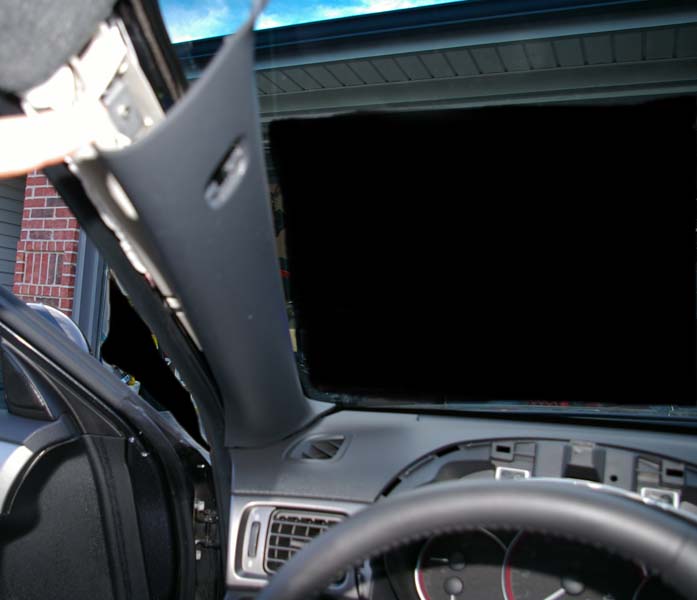
E. Once the pillar trim is removed, you'll see the side curtain air bag. Work carefully around this and insure that all wiring is clear of the air bag so that it won't interfere with deployment in an emergency.
4. Remove the LH Instrument Panel Side Cover
The side panel cover is retained by several push clips. Subaru's shop manual recommends you use a trim tool to pull the panel. An easier way (that avoids the need to buy special tools) is to remove the access door for the fuse block under the left side (traction control) buttons. You can the reach through the opening and push the side cover off from the inside.
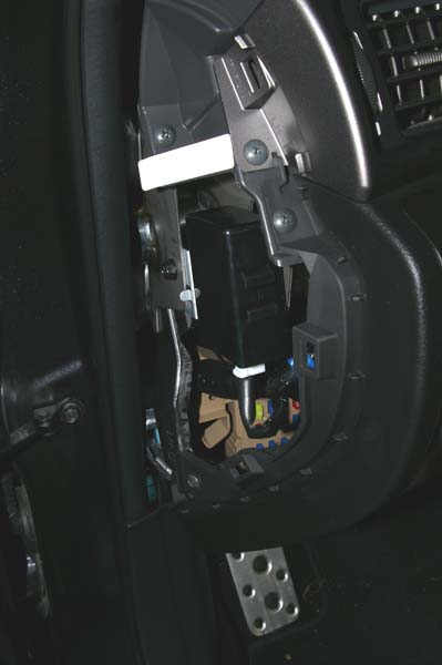
This gives you access for routing your wiring harness as well as to the screw that holds the side vent in place.
This view will be used for the visor, side vent, and gauge cluster removals
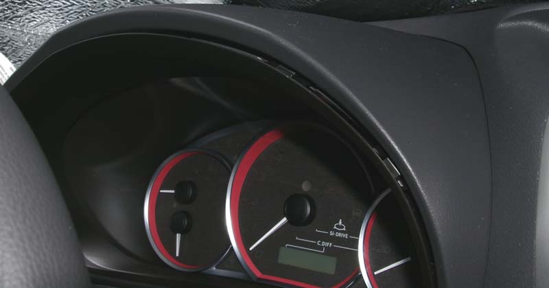
5. Remove the Meter Visor Assembly
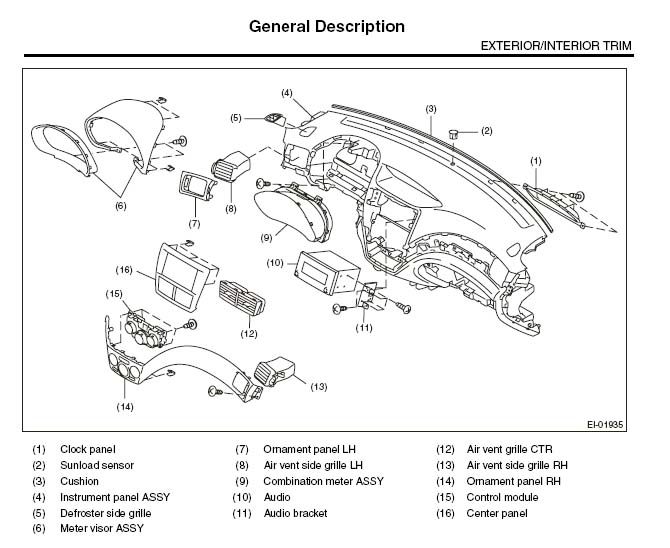
The meter visor assembly is in two parts (6, General). Do NOT attempt to remove the inner trim ring from the larger, outer visor as it's held together using 2 screws that can only be accessed after the whole assembly is removed from the dash. The larger, outer visor is held to the dash using the same type of push connectors as the side cover (step 4).
This view will be used for the visor and gauge cluster removals
A. Lower the steering column and fully extend it toward you to give you room to work (step A2, Combo Meter).
B. Step A3 (Combo Meter) above requires special trim removal tools. Instead, if you can get a solid grip on the entire visor assembly, you can pull it gently straight back towards you. If not, then you may have to separate the upper part of the inner trim ring so you can get a better grip. To separate the inner trim ring, work your finger tips up underneath the lip of the inner trim ring (where it meets the gauge glass) and gently pull it straight down (toward the floor) until the retaining clips separate from the outer visor. You don't have to separate them all; just enough of them so that you can get a solid grip on the outer visor to pull it off the dash. NO NOT TRY TO SEPARATE THE INNER TRIM RING FROM THE VISOR. It is attached by screws that can't be reached until the visor is removed.
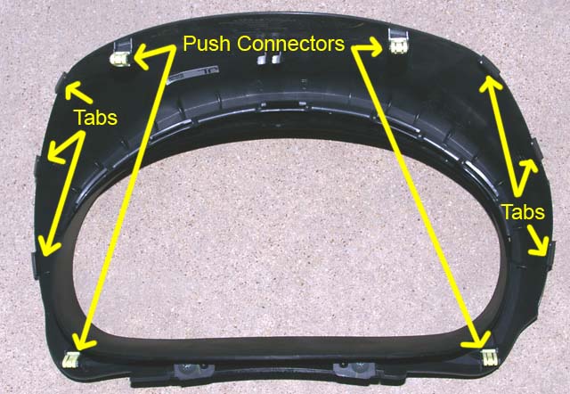
C. There are 4 push connectors as well as a few tabs molded into the outer visor. Pull evenly and gently straight back toward you until they release.
You can see the inner trim screws at the bottom of the visor assembly
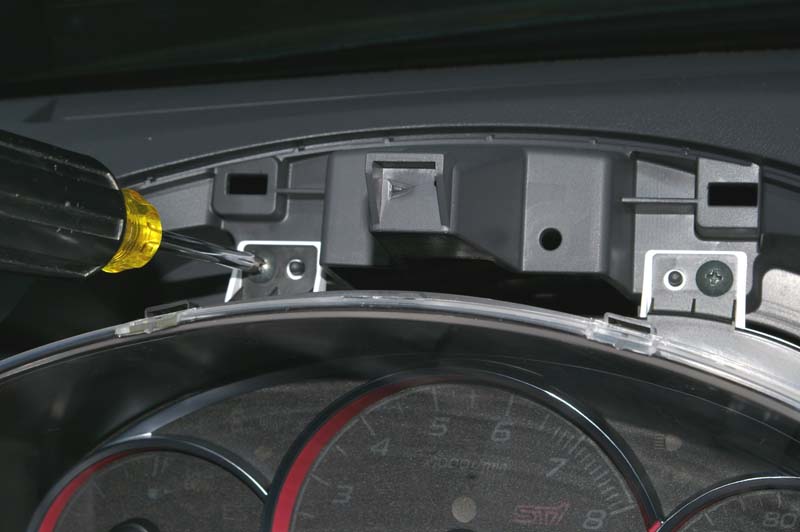
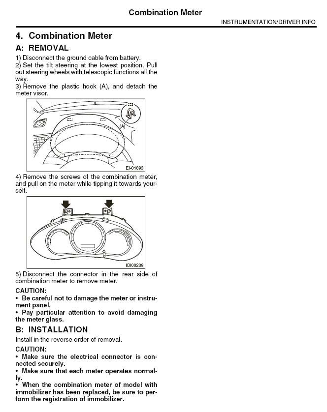
6. Loosen the Combination Meter Assembly (9, General)
We don't need to remove the gauge cluster. We only need to move it out of the way while routing the wiring harness that came with the Custom Thin V1 Remote Display.
A. Remove the 2 upper retaining screws and tilt the top of the meter until the bottom lifts free (A4, Combo Meter).
B. Do not disconnect the gauge from the wiring harness. Simply leave the gauge cluster sitting in place until it's time to route the V1 Remote Display harness.
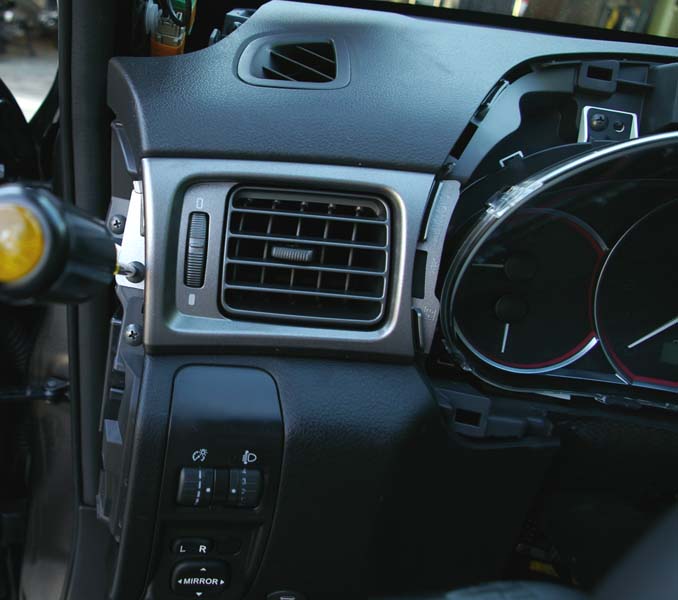
7. Remove the LH Ornament Panel & Air Vent Side Grill (Side Vent)
With the side cover and meter visor removed, you now have access so you can remove the LH Ornament Panel (7, General) and Air Vent Side Grill (8, General).
A. Remove the philips screw to the left of the side vent.
B. Grip the left and right sides of the vent trim with your finger tips and gently pull towards you. The right side is held by clips molded into the trim so work with it as needed to get it to let go. Both parts (7 & 8, General) will come off as an assembly.
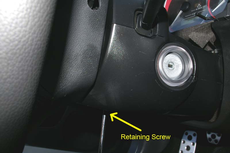
8. Remove the lower steering column cowling
A. Remove the philips head screw from the center of the lower cowling
B. Drop the steering wheel side of the cowl and then slide it out and away from the steering column.
9. Route the wiring harness for the Custom Thin V1 Remote Display
For the 2008 STi, the wiring harness that comes with the remote display is not long enough to reach where I chose to mount the detector. To reach, you'll need to get a 4 foot extension cable (up to 7 feet will work but any longer poses a problem with where to stash the excess). The cable needs to be 4 conductor (4 wire), straight through (no "reversed", swapped, inverted, or other possibilities), RJ11 connectors on both ends, and (ideally) male on one end and female on the other. I had trouble finding a female to male cable, so had to get a male to male with a female coupler. No matter what combination you get, it all has to support 4 wire, straight through, RJ11.
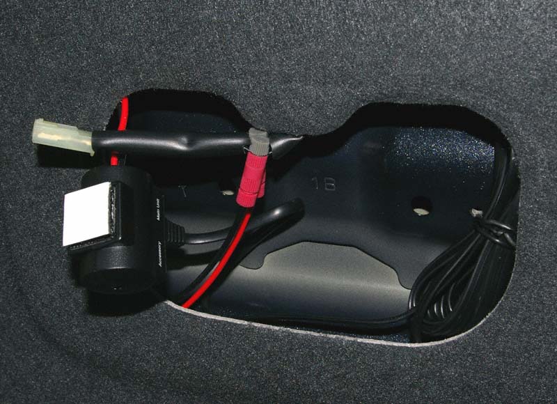
A. Gently pull the head liner away from the windshield near the map light assembly. Feed one end of your extension cable through and out of the map light module hole in the headliner. Leave enough cable so you can easily plug the male connector into the female Accessory socket of the V1 junction box.
B. Work the length of the extension cable into the head liner and over to the pillar by gently pulling the edge of the head liner away from the windshield and tucking the length of cable up into the head liner space as you go.
C. Loosely route the other end of the extension cable down the pillar; leaving the excess hanging for now.
D. Route the end of the Remote Display harness marked "To V1" through the large round hole in the dash that is typically covered by the gauge cluster.
E. Be careful to always leave lots of slack in the harness so that both sides of the "Y" have plenty of slack. The RJ11 jack has to reach the display and the mute button has to reach the turn signal stalk.
F. Reach through the hole where the side vent goes and pull the V1 side of the harness through and under the duct to which the side vent attaches.
G. Feed the V1 side of the harness behind the dash and into the pillar area. Use as much of the OEM wiring retainers (mostly foam) as possible. Make sure that the harness clears the air bag during final assembly. I routed the harness above the various wires and the air bag assembly.
H. Connect the extension cable and remote display harness together (using the coupler if needed); making sure that the combination will tuck into the pillar when the trim is reinstalled.
J. Back at the V1 junction box, gently pull the slack out of the combination extension cable and wiring harness Watch the other end of the harness and always make sure there's plenty on both sides of the "Y".
K. Work on the placement of the RJ11 coupler so that it will tuck into the pillar while allowing the trim to reseat properly during reassembly. I recommend keeping it in the pillar area instead of up in the head liner for easier access if later required.
L. Test for proper function of the V1, remote display, and remote mute button.
M. Bundle the cable slack up near the V1 junction box, twist tie it, and tuck it, the junction box, and the rest of the wires up into the headliner as described in the V1 hard wired installation.
10. Reassemble (reverse steps 1 though 8)
11. Mount the Remote Thin Display and Mute Button
I found that the curve of the visor was not flat enough for the included sticky tape to grab. The Custom Thin Remote Display kept pulling loose. Instead, I used some 3M Dual Lock. I have used this stuff for years for installations that require a stronger grip than Velcro can provide. You can usually find it at Radio Shack, Office Depot, and other supply houses (as well as on the internet).
A. Make sure your hands are clean and dry before handling the adhesive tape of the 3M Dual Lock or the sticky tape that came with the harness.
B. DO NOT attach the harness to the remote display at this time.
C. Check to proper clearance/slack so the harness can plug into the remote display without pulling or pushing on the remote display.
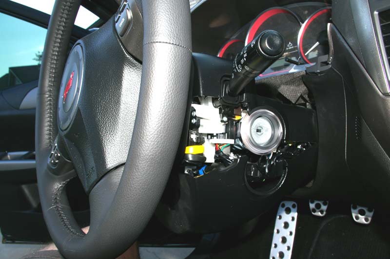
D. Check for proper clearance/slack so the remote mute button will stick to the back side of the turn signal stalk.
E. Clean the mounting locations for both the remote display and remote mute button with the included alcohol swabs.
F. Mount the remote mute button to the back of the turn signal stalk.
G. Cut 2 strips of 3M Dual Lock to size so that it runs the width of the remote display and is about half an inch thick (about one half inch by 3 inches).
H. Stick one side of the 3M Dual Lock to the remote display, snap the other section of Dual Lock to the first, align the remote display under the visor and stick the entire assembly in place.
I. Allow several hours for the adhesive to set firmly before plugging the harness into the remote display.
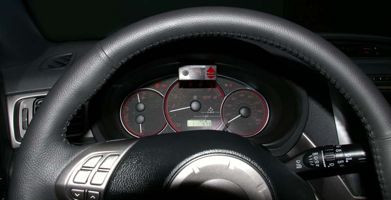
The finished installation.
(C) 1995 - Present. Mark Johnson. All rights reserved.